Flash Code
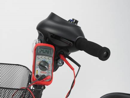
1,2,&3 Battery Voltage -
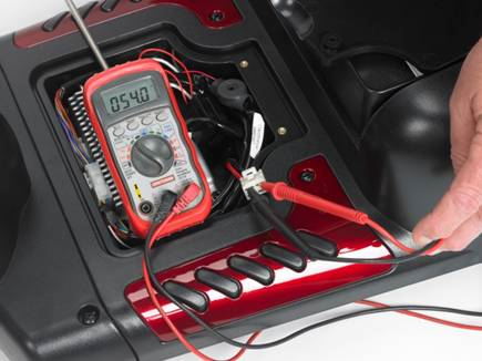
The voltage should read between 22 and 28 volts.
If the reading is too low, recharge/ replace the batteries.
If the reading is too high, the charger is not shutting itself off and is overcharging the batteries and must be replaced.
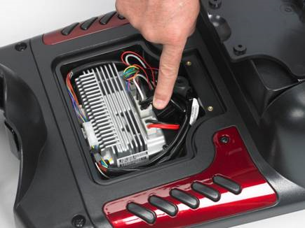
5 Controller does not “see” the electromagnetic brake.-
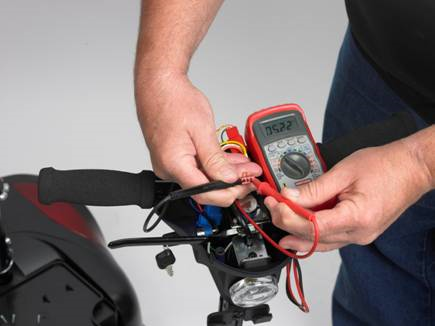
Locate the white motor/brake connector on the controller and unplug it.
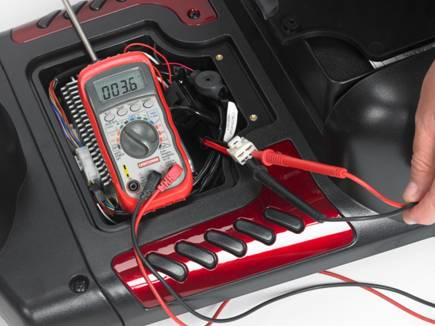
Set your multimeter to the Ohms function on the RX200 scale, and insert the test leads into the two lower contacts and read the resistance of the motor armature.
It should read between 1 and 5 ohms.
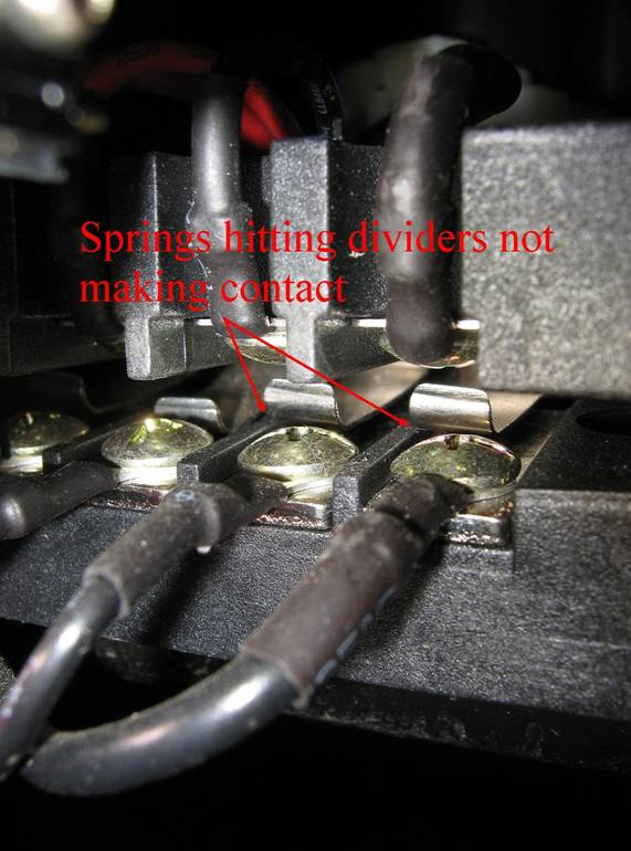
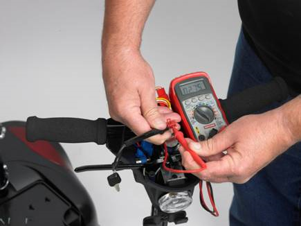
Now insert the test leads into the two upper contacts and measure the electromagnetic brake resistance (the brake must be set in the “drive” position)
It should read between 45 and 60 ohms. If there is no reading, check the two front to rear contact blocks to see if the contacts are misaligned, or that they might be dirty or melted.
If they are misaligned follow the procedure for realigning them. If they are correctly aligned measure the brake and armature resistance at the motor, or at the rear contact block.
6 The throttle is not in the neutral position.
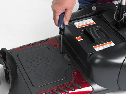
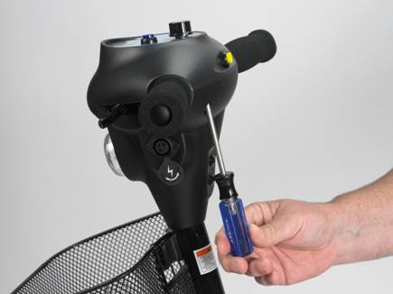
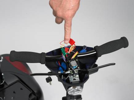
A. Remove the 6 screws that secure the tiller cover and lift it out of the way.
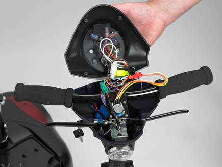
B. Locate the Forward-
C. With your ohmmeter set on the 20K scale measure the two outside terminals of the throttle potentiometer. You should measure approximately 5K ohms. Now measure from each outside terminal to the center terminal. Both readings should be equal , + or – 100 ohms. If there is no reading at all in any measurement then the throttle assembly should be replaced. If there is an imbalance, then the neutral position can be adjusted by loosening the set screws and turning the potentiometer shaft to the “electrical” center point and tightening.
8 Flashes-
9 Flashes-
 Home
Home