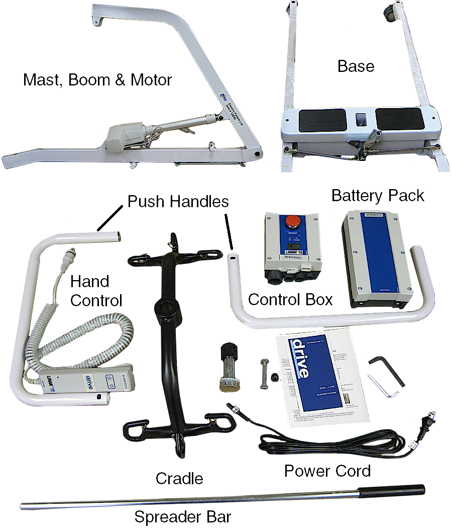
1. Unpack the unit. Identify and verify that all parts are present.
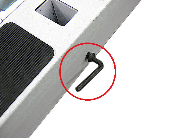
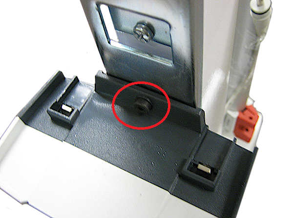
2. Remove the Allen head cap screw from the base of the unit with the provided Allen wrench.
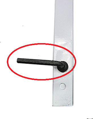
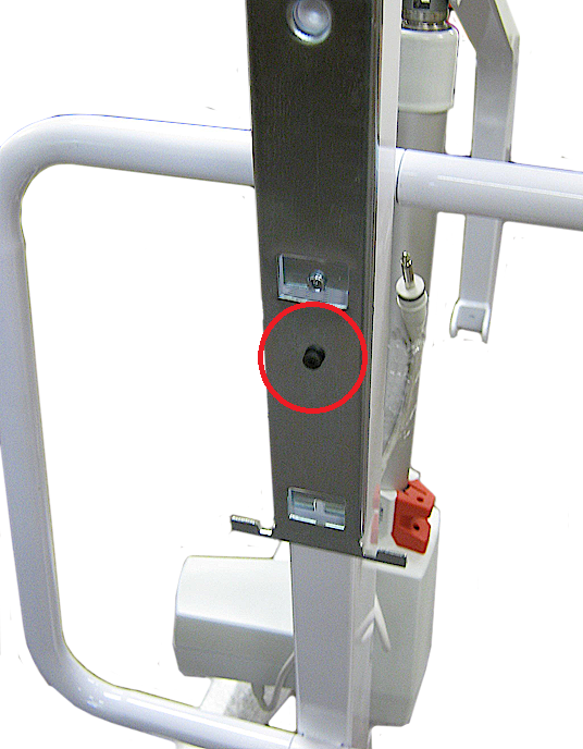
3. Remove the Allen head cap screw from the mast of the unit with the provided Allen wrench.
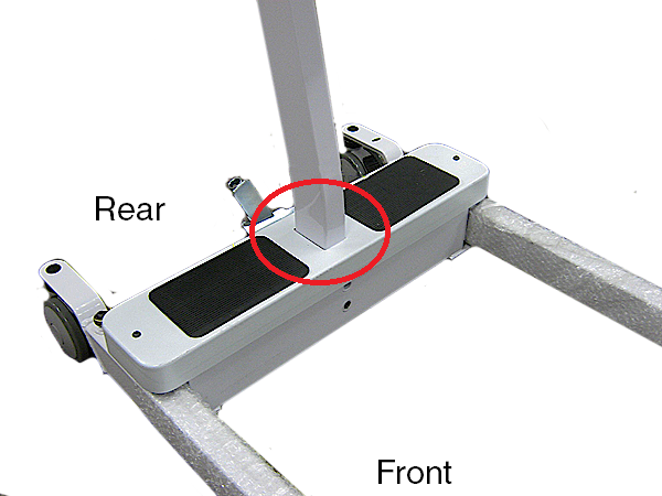
4. Install the mast into the base with the boom towards the front of the base.
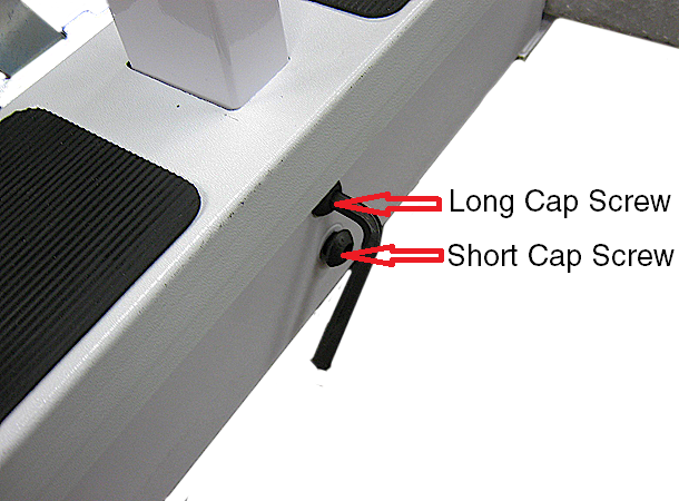
5. Install and tighten the two Allen cap screws with the provided Allen wrench. The longer cap screw goes on top and the shorter cap screw goes on the bottom.
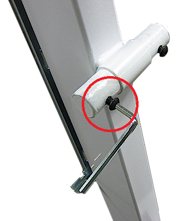
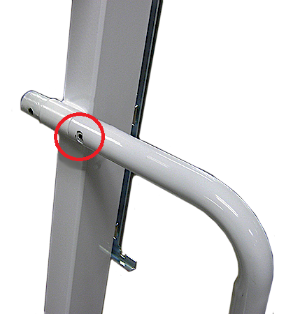
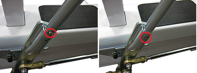
6. Remove the Allen cap screw from the upper and lower push handle posts with the Allen wrench provided.
7. Slide one of the push handles over the upper and lower posts. Make sure the holes line up.
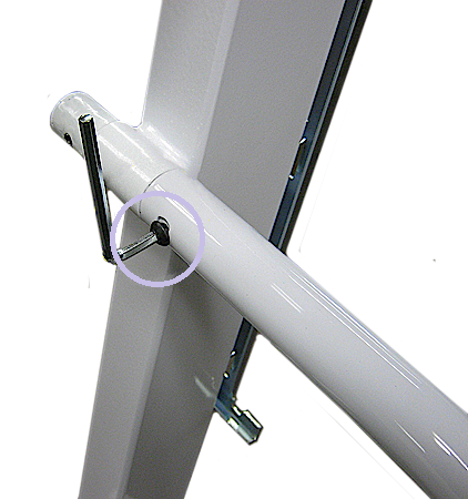
8. Install and tighten one of the Allen caps screw that were remove in the upper and lower push handle post. Repeat steps 7 and 8 for the other side.
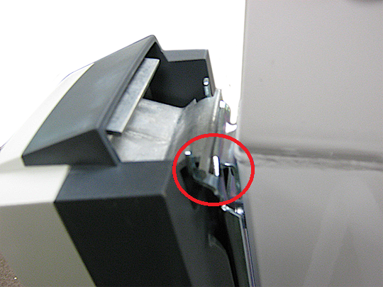
9. Remove the small screw from mounting bracket.
10. Slide the control box on to the lower bracket and install the small screw previously removed.
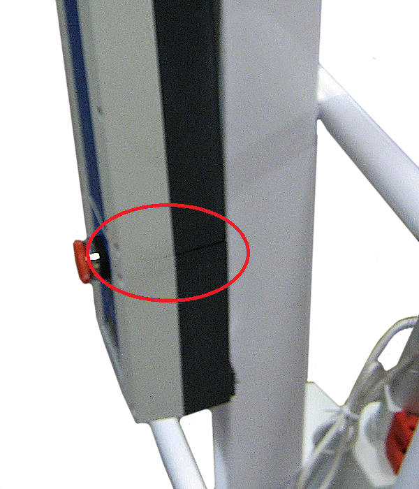
11. Line up the battery pack with the control box.
12. Pull up on the locking latch release on the battery pack.
13. Push the battery pack over the upper bracket and release the locking latch to lock in place.
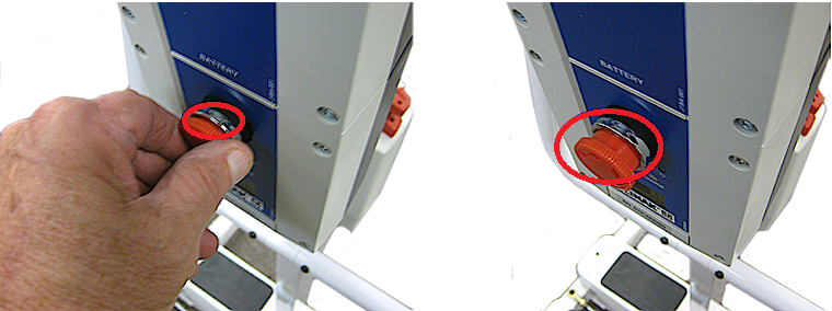
14. Verify that the emergency stop button is not pushed in. If the emergency stop button is pushed in, turn the button to reset it to the out position. The emergency stop button has to be in the out position for the lift to operate.
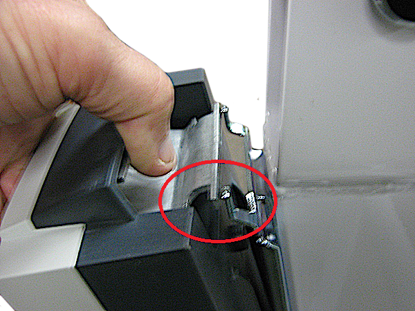
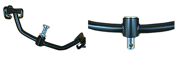
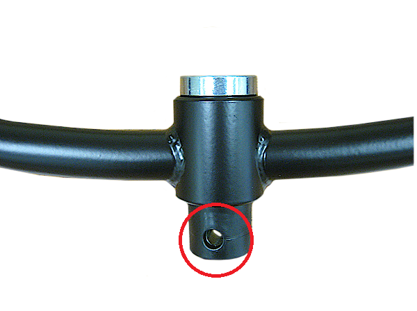
15. Insert the spreader bar into the receiver plate and depress the locking button. Continue to insert the spreader into the receiver plate until it locks into place.
16. Insert the cradle swivel pin and nylon washer into the cradle.
17. Install the nylon cover over the cradle swivel pin and line up the holes of both.
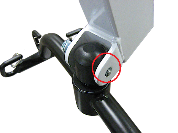
18. Align the holes of the cradle pin and cap with the holes in the U bracket at the end of the boom. Insert the bolt through the holes.
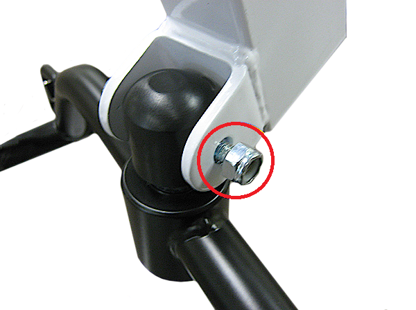
19. Install the nut on the bolt and tighten.
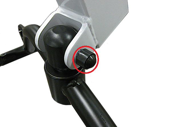
20. Install the nut cap on the nut.
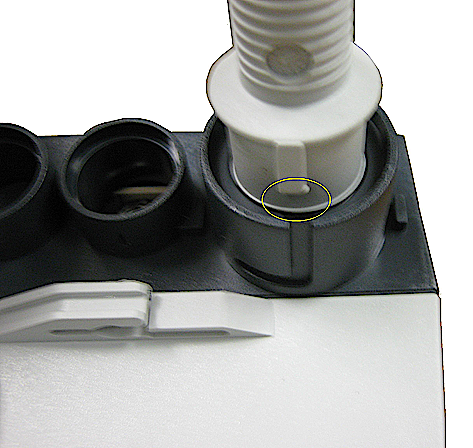
21. Align the tab on the plug of the hand control with the indent in the hand control socket.
22. The plug must be pushed in flush with the controller. If there is any difficulty when inserting the plug a very small amount of petroleum jelly on the rubber O ring is required.
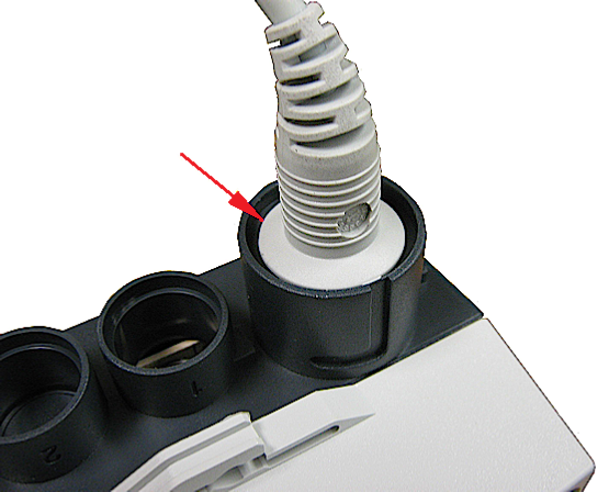
23. Put for the connector for the motor actuator cable into small round socket on the controller.
24. The plug must be pushed in flush with the controller. If there is any difficulty when inserting the plug a very small amount of petroleum jelly on the rubber O ring is required.
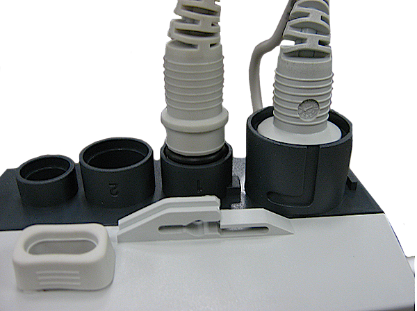
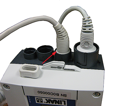
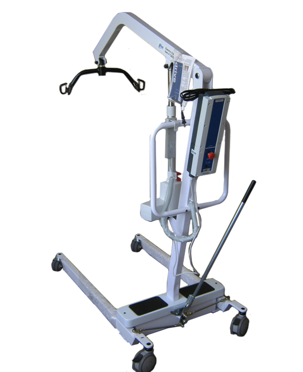
25. The lift is now fully assembled.
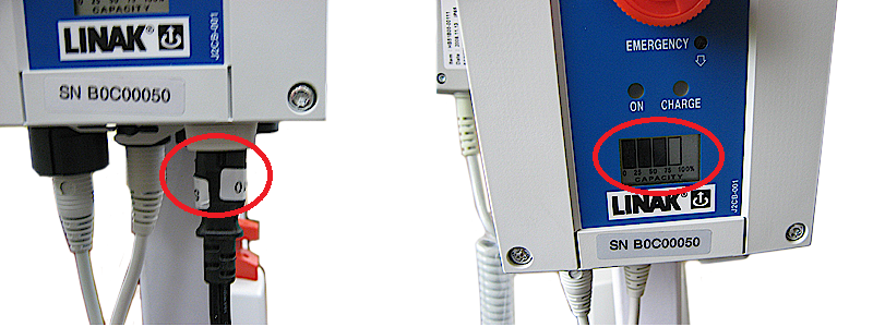
26. Charge the unit by plug the charger cord into the controller and a wall socket. The amount of charge on the battery is indicated by the bar gauge on the front of the unit. The charger plug must be disconnected from the lift for the lift to work.
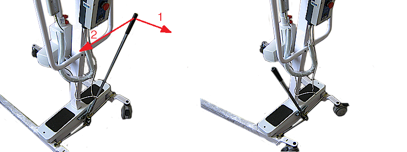
27. To spread or close the legs of the lift (1) pull back on the spreader bar and (2) shift to the opposite side.
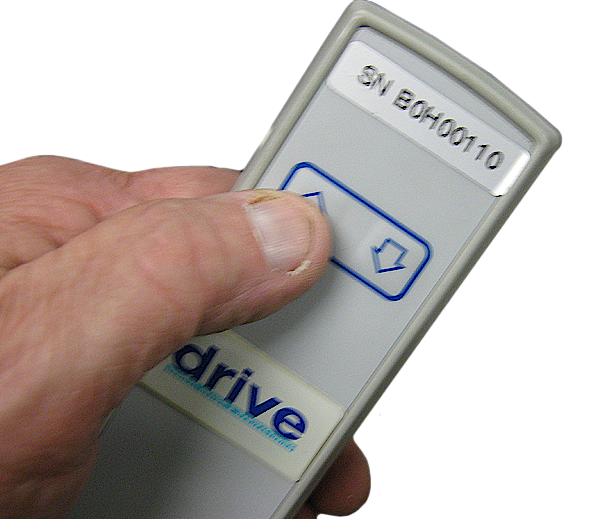
28. To operate the lift use the up and down arrow on the hand control.

 Home
Home