Code 21( 2 short,1 long beep)-
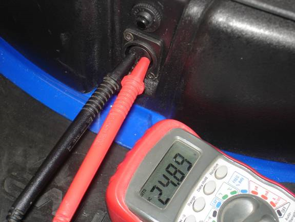
Set your test meter to the 50 volt DC scale and insert the two test leads into the charger port on the battery box.
If the voltage reading is lower than 23 volts charge the battery pack for 6 hours. Take another measurement. If the voltage is still low replace the batteries.
Code 22 (2 short,2 long)-
TO REPLACE THE CONTROLLER
1. Remove the battery pack.
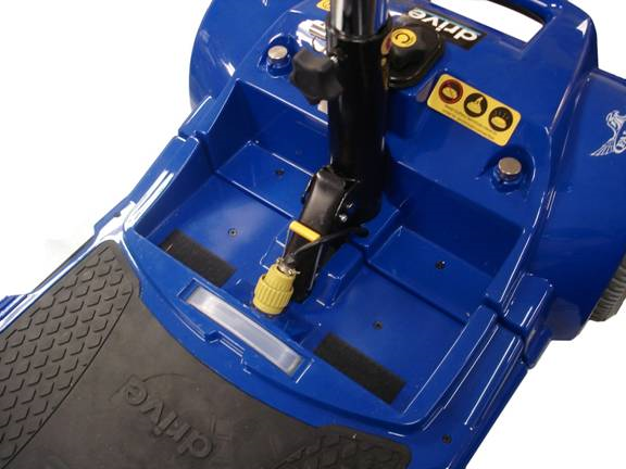
2. Unplug the front-
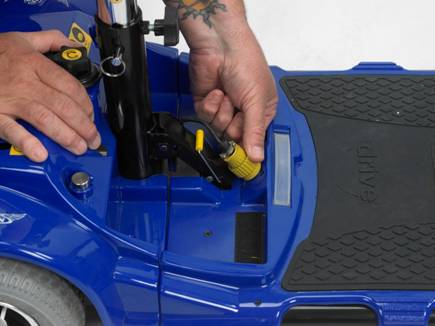
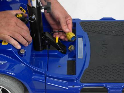
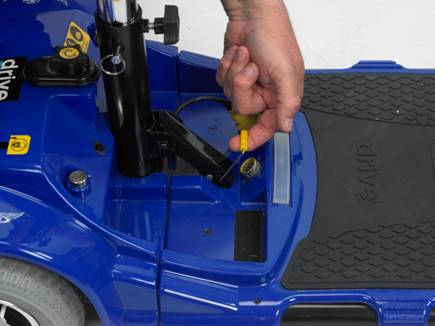
3. Grasp the yellow release handle and lift. The rear section will roll onto its back bumper.
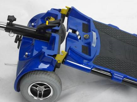
4. Separate the front from the back sections.
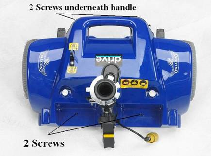
5. Remove 4 Phillips head screws and lift the rear shroud to gain access to the controller.
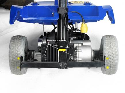
6. Unplug the electrical connectors from the controller and remove the 4 screws securing it to the frame. Remove the controller and replace using the preceding steps in reverse order.
Code 23 (2 short,3 long)-
Code 24 (2 short,4 long)-
If any wires are shorted to each other, correct the fault or replace the harness. If the harness checks out good, replace the controller.
Replace the controller as outlined in Code22.
Code 25 (2 short,5 long)-
TO REPLACE THE PCB
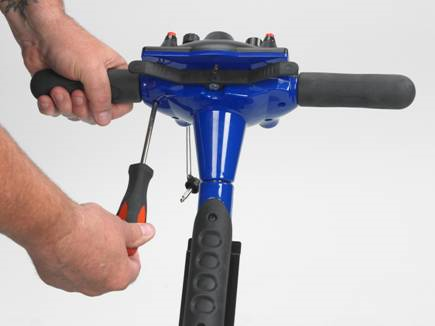
1. Tilt the tiller forward for easier access to the underside of the console.
2. Remove the 6 screws that hold the top panel to the tiller.
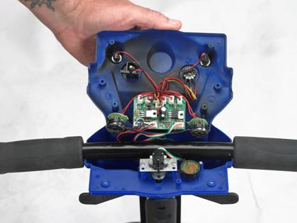
3. Lift the lid off the tiller. Note that several plugs have the same colored wires. Unplug one connector at a time from the old PCB and plug it into the new PCB to avoid having the new PCB wired incorrectly.
4. When the connectors are all transferred, dismount the old PCB and mount the new one in its place.
5. Reinstall the console to the tiller.
Code 26 (2 short,6 long)-
1. Gain access to the controller as described in Code 22.
2. Remove the motor plug from the controller.
3. With your ohmmeter set in the 200 ohms function measure the brake resistance at the plug. You should measure between 40 and 70 ohms. (brake must be set in the “drive” position). If there is less than 40 ohms, or no reading at all, then the brake is defective.
Since the brake/motor/transaxle is sold as one assembly, the whole motor/transaxle must be replaced. Remove the mounting bolts that hold the transaxle to the chassis. Lift out the old transaxle and replace with the new one. Install the bolts and tighten securely.
 Home
Home