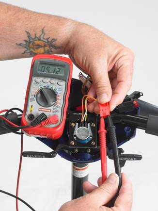
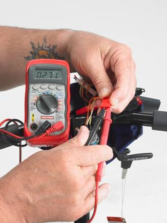
You should read 5K Ohms, + or – 20%.
4. Measure from one outside terminal to the middle terminal and note your findings.
5. Now measure from the other outside terminal to the middle.
Your two readings should be within 100 ohms of each other. If they are out of tolerance loosen the set screws on the assembly and adjust the electrical center point until they are within 100 ohms of each other. If this cannot be accomplished, replace the forward-
1,3-
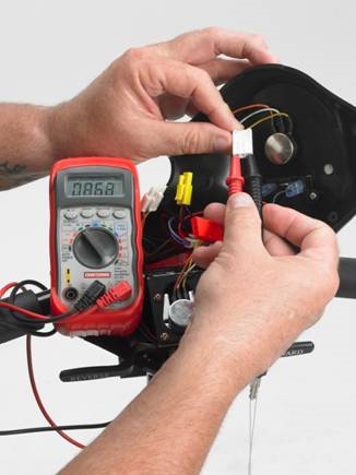
1. Remove the tiller cover. Refer to the procedure described in 1,2 to gain access.
2. Unplug the speed pot connector from the main harness.
3. With your multi meter set on the 200K Ohm position measure the two outside terminals. You should read 100K ohms,+ or – 20%.
4. Put one test lead on the center terminal of the speed pot and the other on either end terminal. Rotate the knob from one end to the other. You should see the reading change from 0 to 100K, or , 100K to 0, depending on which terminal you selected. If there are any non linear or open spots on the control it should be replaced, p/n BC31001.
1,4 -
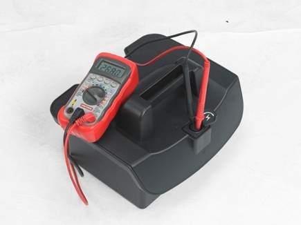
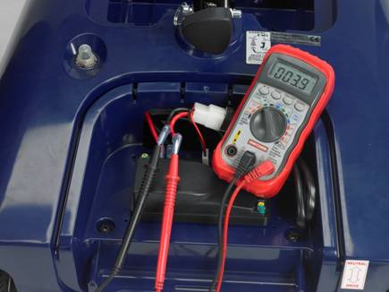
On a fully charged battery pack you should be reading 26.5-
1,5-
3,2-
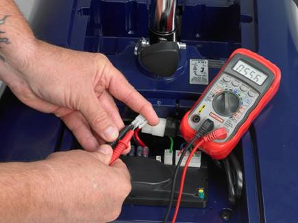
Make sure that the scooter is not in the “Freewheel” mode. If it is, then push the red lever behind the right rear wheel to lock the brake.
1. If it is not, gain access to the controller by removing the black rear controller shroud.
2. On the controller, locate the white 2 pin connector with the thin red and black wires, and unplug it. With your test meter in the 200 Ohm function, insert your test leads into the two terminals of the connector.
You should read approximately 45-
3,4-
Problems with no fault code displayed .
1. If all the lights are lit but the chair does not drive, check that the charger is not plugged into the battery pack. If it is, the scooter goes into the “inhibit” mode.
2. If all the lights are on, the scooter does not drive, but you can hear the electromagnetic brake “click” when you press the throttle, suspect that the motor is at fault.
A. Remove the black back shroud to expose the controller.
B. Locate and unplug the large red and black wires which are between the large red and black battery wires and the brake connector.
C. With your meter set at the 200 ohm scale insert the test probes into the motor plugs.
You should read between 2 and 6 ohms. If you get no reading or a direct short circuit, the motor is bad and must be replaced, p/n BC31125.
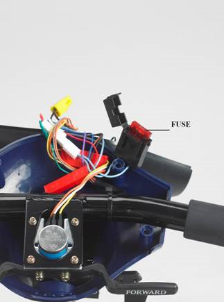
3. If you turn the key on and the scooter does not light or respond press the reset button on the rear shroud. If that does not fix the problem, locate the fuse by removing the control panel on the tiller.
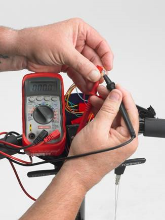
Open the fuse holder and remove the fuse. Set your multi meter to the 200 ohm scale. Touch the red test probe to one blade of the fuse while touching the other blade with the black probe. If there is no continuity the fuse is bad and must be replaced.
1 flash, pause, 1 flash(1,1)-
1,2-
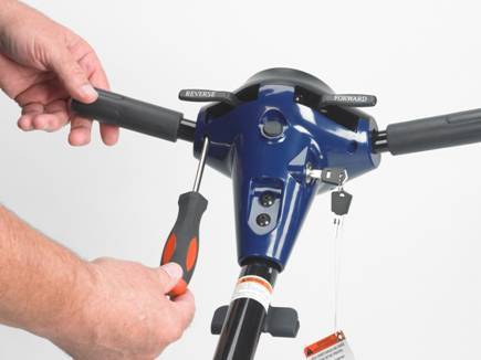
To gain access to the components in the tiller assembly:
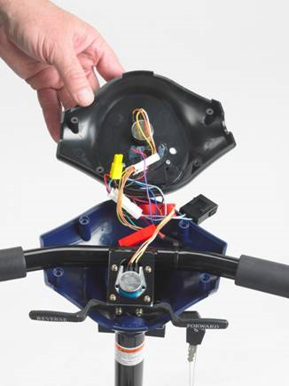
1. Remove the six screws underneath the tiller and lift the panel off.
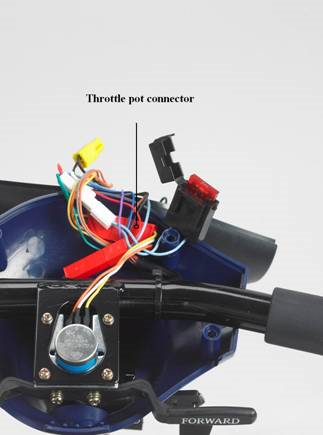
2. Unplug the throttle pot from the harness.
3. With your test meter set in the OHMS 20K function place the test leads on the outside terminals of the throttle potentiometer.