INTRODUCTION
The CTE throttle control replaces the 5K resistive throttle pot used in most scooters. It cannot be tested in the conventional way with an ohm meter, as it is not a variable resistor.
In order to ascertain the condition of the throttle control it must be tested in the circuit, powered up. Unless power is applied to the connector with the red and black wires, the throttle will not control the circuit. If a reading is attempted by disconnecting the 3 pin connector and probing directly at the connector, no output will be read, even with power applied to the 2 pin connector.
THIS TEST CAN BE DONE WITH THE SCOOTER IN FREEWHEEL MODE
If you choose to not use the freewheel mode, lift the rear of the scooter and block the wheels off the ground.
1. Turn on the scooter.
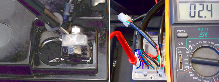
2. Locate the multi-
3. With your multi-
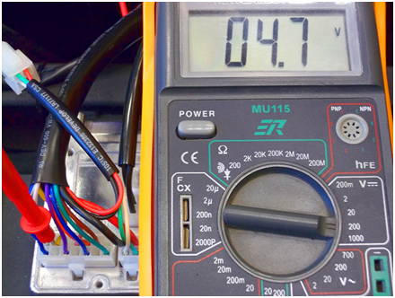
4. Move the test probe to pin 2 (yellow wire). You should be reading approximately 4.7 Volts DC, +or -
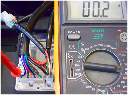
5. Now move the test probe to pin 8 (blue wire). You should be reading approximately .3 volts DC, +or -
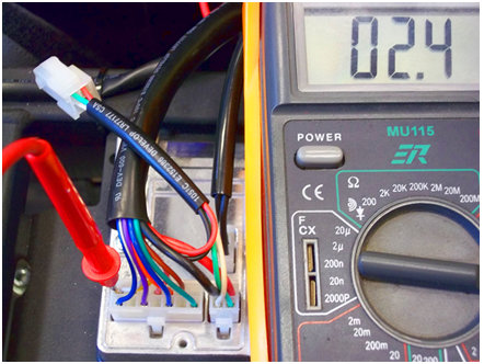
6. Move the probe back to pin 1 (white wire). As you monitor the voltmeter, slowly push the throttle paddle, first forward, then backward. As you move in one direction the voltage will count up or down (depending on the direction you push), in proportion with the swing of the throttle blade. There should be no dead spots or spikes in the voltage readings. At the highest point you should read within .2 volts of the high you read before with the paddle in neutral. The low should be within .2 volts of the low reading you took before.
7. Return the paddle back to neutral and reread the center and end point voltages. They should be the same as before. This will ensure that the throttle is returning to its center point.


 Home
Home